
Numerical analysis of welded structures is becoming more commonly accepted in the field of engineering safety. This brings new challenges, such as assessing residual stresses in ferritic (iron) steel welds, which are complex due to the structural changes that occur during welding. The following research highlights a solid-state phase transformation model that has been developed to predict these structural changes.
Ultimately, this weld model may be used to optimise the welding process used for ferritic steels, which may help extend the service life of welded components.
|
|
|
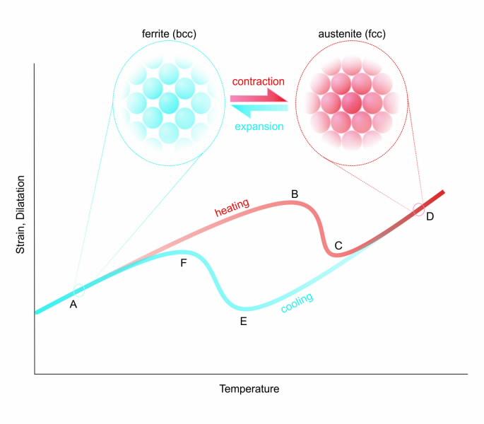
Representative thermo-mechanical cycle in ferritic steel welding processes. The weldment first undergoes heating (line A-B-C-D): as bcc ferrite is heated to point B, the metal experiences thermal expansion. Between points B and C, the crystal structure transforms from ferrite to austenite, resulting in a contraction of the metal due to the increased atomic density of fcc metal. The inverse cycle occurs upon cooling (line D-E-F-A); a variation in transformation temperatures exists (point E vs. point B) due to the rapid heating and cooling rates involved in the welding process, which delays the transformation process. |
The numerical analysis of welded structures
The study of welds – most importantly, the residual stresses induced during welding – is receiving greater attention within a wide range of engineering fields.
In general, residual stresses are confined internal stresses that exist in a structural component in the absence of external loading or thermal gradient. Weld-induced residual stresses are a particular concern in safetycritical components and assemblies, since these stresses may lead to the premature failure of a given system.
One of the most common failure methods is the creation and propagation of cracks that develop in or near welds; the problem of premature cracking is exacerbated by the presence of a severe thermal or corrosive environment. For this reason, the effects of welds are considered when performing remaining-life assessments and safety inspection schedules for the power generation industry, where a complex system of welded components and piping are used to produce and deliver steam to turbines.
As the cost associated with extensive experimental analyses can be prohibitive, simulations via numerical analyses are employed to predict the weld-induced residual stress field in a component. These predicted stresses may then be used to study the in-service structural integrity of an object.
The importance of solid-state phase transformations
Currently, finite-element models are capable of accurately predicting the residual stress field (and the resultant distortion) in a wide variety of welds.
Preliminary benchmark studies were performed in single-pass welded structures, where a weld is made by depositing filler metal during a solitary pass of the welding torch.
Subsequent work has been successfully performed in multi-pass welds, where tens or hundreds of weld passes may be required to deposit the necessary amount of filler metal; these welds are more complex due to thermal cycling in the metal surrounding the weld, as the welding torch repeatedly heats the material and it then cools between each pass.
To a similar extent, the types of materials involved in a welding process display a varying level of complexity when simulating their behaviour. Most weld studies have focused on commonly used pressure vessel and piping materials, including austenitic stainless steel and nickel-based superalloys.
However, austenitic steel welds are well understood, straightforward processes to model when compared to their ferritic steel counterparts (which are also frequently used for piping); the reason for this discrepancy stems from the crystal structure found in each material. As illustrated in Fig. 1 (see image library below), austenite possesses a face-centred cubic (fcc) lattice, whereas ferritic steel is predominantly body-centred cubic (bcc).
The iron (Fe) atoms are arranged closer in a fcc steel relative to a bcc steel; should a bcc-fcc transformation of phases occur, volumetric shrinkage of the transforming material is observed. In contrast, the occurrence of an fcc-bcc transformation would result in a volumetric expansion of the transformed material.
While austenitic steels are stable through a wide range of temperatures, the extreme heating and cooling encountered during welding of ferritic steels causes a phase transition in the metal (Fig. 1); from a bcc structure to an fcc structure during heating/welding and an inverse transition upon cooling. The structural changes associated with these phase transformations can have a dramatic effect on the final residual stress field in a ferritic steel weldment.
The transformation kinetics involved are complex and dependent on a number of variables, which is why many current numerical weld analyses use simplified approximations of the phenomena, or exclude these transformations entirely.
Developing a model
Research conducted within ANSTO’s Structural Integrity group is currently focused on identifying the key material parameters required to predict solid-state phase transformation kinetics during welding of ferritic steels.
The present approach employs a semi-empirical methodology developed by Kirkaldy and Venugopalan [1], whereby the chemical composition and the average grain size of the steel are the main parameters required to calibrate the model. Such an approach is advantageous because many other models require a set of experimental analyses be carried out for model calibration.
The essentials of the Kirkaldy-Venugopalan model have been integrated into a user-defined subroutine for the ABAQUS finite-element package, which is the software package currently used within our Institute to predict weld-induced residual stresses [2].
Model validation
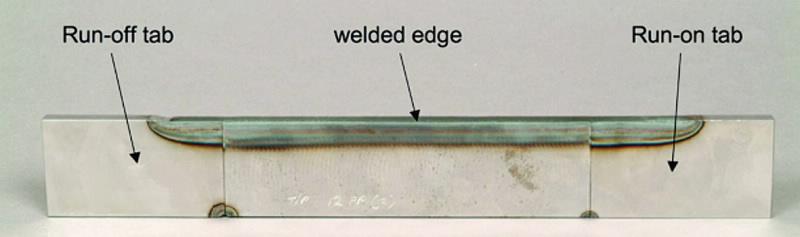
To test the accuracy of the ABAQUS subroutine, a weld model has been constructed in collaboration with the European Network on Neutron Techniques Standardisation for Structural Integrity (NeT), via a Task Group (TG5) that is concerned primarily with the analysis of ferritic steel welds. Within this task group, a series of autogenous beam welds have been laid on specimens of ferritic steel commonly used for power plant components (SA508 Gr.3 Cl.1 steel) using a conventional gas metal arc welding technique; Fig. 2 shows one of the welded samples.
Two sets of samples were produced, with the primary variable being the speed at which the welding torch passes across the weldment (i.e. the torch speed). One set of samples was prepared with a torch speed of 5 mm/s, while a second set of samples was prepared using a torch speed of 1.25 mm/s.
These variations in the welding torch speed have resulted in different heating and cooling rates during welding, and consequently in different steadystate microstructures observed in each sample set.
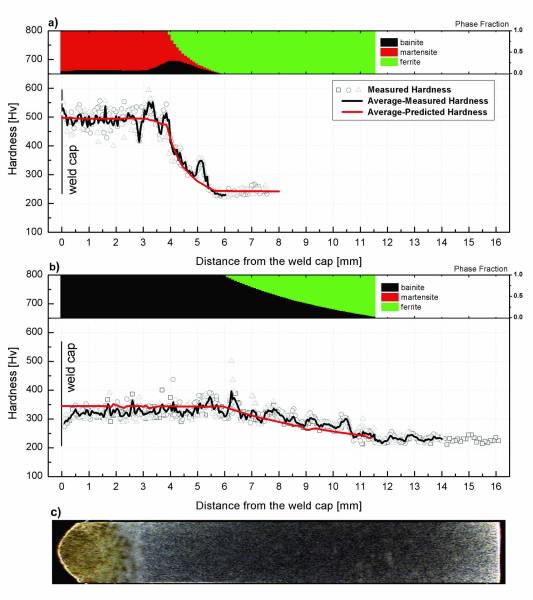
Predictions of these phase compositions have been made using an ABAQUS thermal analysis, calibrated using thermocouple data taken during the welding studies. Once an accurate thermal history is reproduced in the model, the predicted phase composition is captured. Using an approach developed by Maynier et al. [3], the phase distribution and chemical composition of the steel can be used to predict the local hardness of the heat-affected weld metal.
This phase-specific hardness data can then be compared to measured microhardness data, which has been collected from the samples using a Nano Indenter G300 [4]. Fig. 3 compares the predicted hardness profiles of both sample sets to measured values. Good agreement can be seen in each study, thus validating the phasetransformation subroutine developed.
|
| Representative TG5 sample: an autogenous beam weld in SA508 Gr.3 Cl.1 steel, with run-on and run-off tabs to ensure a uniform weld bead is laid on the specimen. Dimensions are 180 x 10 x 50 mm3 (l x w x h). |
|
|
Predicted post-weld steady-state phase compositions with torch speeds of: (a) 5.00 mm/s; and (b) 1.25 mm/s. Phases are validated via hardness profiles. (c) A representative steady-state beam weld profile in SA508 steel (not to scale). |
Outlook
The successful prediction of phase composition in ferritic steel welds is merely the first step of a comprehensive structural integrity analysis for safety-critical engineering components. Subsequent analyses will attempt to validate the residual stress profiles predicted with a fully coupled thermo-mechanical weld model in ABAQUS, using measurements of the NeT TG5 samples via the Kowari stress diffractometer at ANSTO [5].
Once the model has been fully validated, studies may be conducted to predict the susceptibility of such welds to cracking, and to ascertain what effect the presence of welds may have to safety inspection schedules and the remaining-life assessment of welded structures.
Ultimately, these weld models may be used to optimise the welding process used for ferritic steels, in an attempt to extend the service life of welded components.
Authors
Cory Hamelin, Ondrej Muránsky, Philip Bendeich, Lyndon Edwards
ANSTO
References
- J.S. Kirkaldy and D. Venugopalan, in: Phase Transformations in Ferrous Alloys, edited by A.R. Marder and J.I. Goldstein, TMS Publications, Warrendale PA, 125-148 (1984).
- O. Muránsky, C.J. Hamelin, M.C. Smith, P.J. Bendeich and L. Edwards, The effect of plasticity theory on predicted residual stress fields in numerical weld analyses, Computational Materials Science, 54, 125-134 (2012).
- P. Maynier, J. Dollet and P. Bastien, in: Hardenability Concepts with Applications to Steels, edited by D.V. Doane and J.S. Kirkaldy, AIME, New York, NY, 518-544 (1978).
- C.J. Hamelin, O. Muránsky, P.J. Bendeich, K. Short and L. Edwards, Predicting solid-state phase transformations during welding of ferritic steels, Materials Science Forum, 706-709, 1403-1408 (2012).
- O. Kirstein, V. Luzin, A. Brule, H. Nguyen and D. Tawfik, Kowari – OPAL’s residual stress diffractometer and its application to materials science and engineering, Advanced Materials Research, 41-42, 439-444 (2008).