Beamline Capabilities
The Micro-Computed Tomography (MCT) beamline at the Australian Synchrotron (ANSTO) provides advanced three-dimensional X-ray imaging with micron-scale resolution, reaching up to 1 µm. As the first of the eight new BRIGHT beamlines, it has been in successful user operation since October 2022. The beamline uses monochromatic (8–40 keV), pink, and white X-ray beams to deliver detailed structural information across a wide variety of samples.
Its primary techniques are absorption-contrast and propagation-based phase-contrast imaging, complemented by advanced methods such as dark-field, grating-based, and speckle-based imaging for specialised applications. Additional capabilities include tomosynthesis, helical scanning, and rapid two-dimensional imaging of dynamic processes. Future developments will bring a robotic stage for automated high-throughput sample exchange, laminography, a nano-CT configuration based on Fresnel zone plates, and environmental stages for high temperature and mechanical loading—developed in collaboration with user groups.
Data collection, reconstruction, segmentation, and visualization are supported by innovative software tools, specialised phase-retrieval algorithms, and high-performance computing infrastructure, ensuring efficient workflows from acquisition through to analysis.
For more information of the MCT beamline, see the link below:
https://asuserwiki.atlassian.net/wiki/spaces/UO/pages/1516601345/MCT+Beamline
Scientific Applications
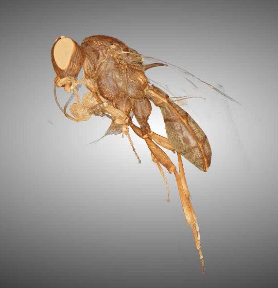
The MCT beamline enables non-destructive 3D characterisation across diverse fields, including biomedical and health sciences, food science, geosciences, materials science, and palaeontology. It was designed to meet the needs of both academic and industry users seeking detailed structural insights into materials.
Key applications include:
Investigating failure mechanisms in 3D-printed components and alloy systems.
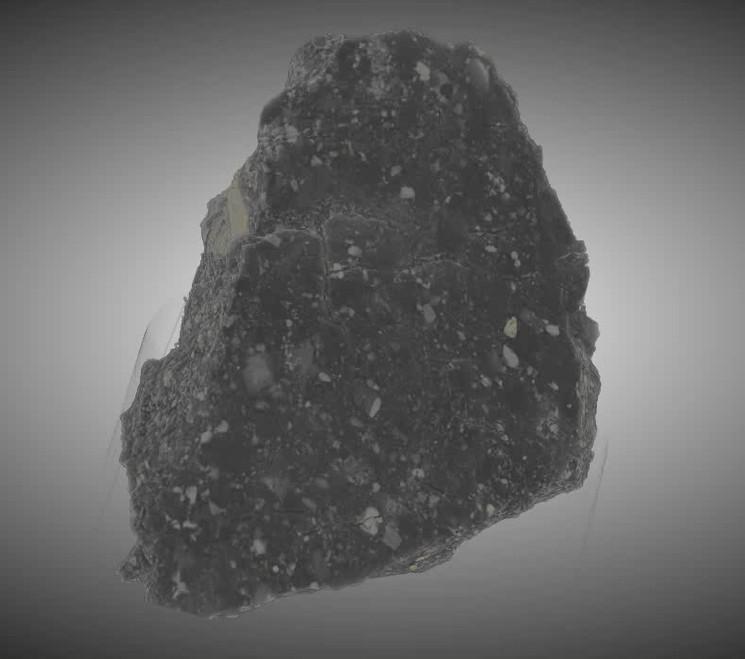
Quantifying micro-porosity (e.g., pore size, shape, connectivity, and tortuosity) in rocks and shales for petroleum research.
Understanding structural properties of coal and coke.
In situ studies of bone response under load and tensile testing.
Characterising phase transitions in materials under varying temperature or pressure.
Enhancing contrast in soft- and hard-tissue studies using low-energy X-rays.
Pyrolysis studies of biomass systems.
High-resolution analysis of fibres and yarns.
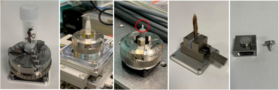
Non-destructive imaging of small fossils, including specimens in amber.
For more detail of the MCT potential application, see the link below:
https://asuserwiki.atlassian.net/wiki/spaces/UO/pages/1606123605/Potential+Applications
Technical Information and Specifications
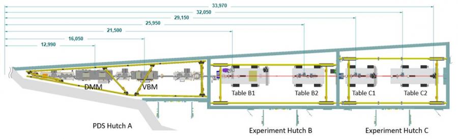
The MCT beamline comprises three hutches centred at approximately 15, 24 and 31 m from the bending-magnet source point. The first hutch (the first optical enclosure) houses the photon-delivery system, including mask, slits, collimator, DMM, VBM, diagnostics and shutters. The X-ray beam travels in vacuum until it passes through the Be window at the entrance to the second hutch, approximately 20 m from the source. The second and third hutches constitute the end stations for conducting user experiments. When the experiments are in the second hutch, a beam stop at the downstream end provides for safe and open access to the third hutch. When the experiments are in the third hutch, the second hutch is searched and secured.
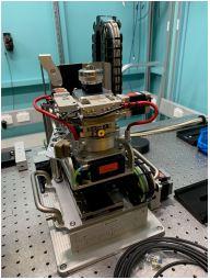
Each of the experimental end stations house two large, stable optical tables to support experimental equipment. These tables can be adjusted in height and (for the first end station) tilt, so that a fixed offset is maintained between the table surface and the X-ray beam for any configuration of the DMM and VBM in the photon-delivery system.
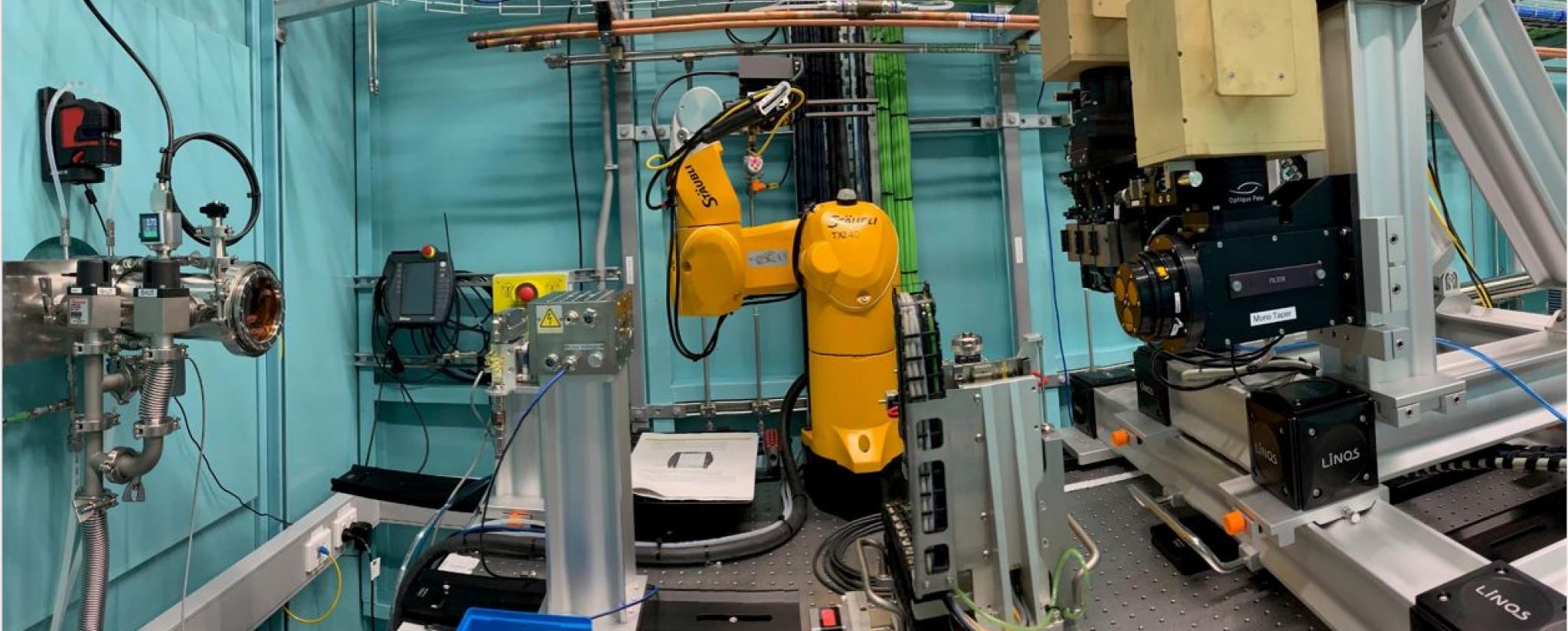
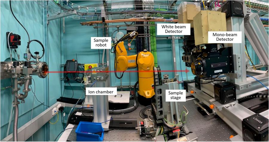
The first experimental hutch houses the sample-exchange robot that is fixed on the first experimental table, and will operate with the primary CT sample stage. Standard, absorption-contrast and propagation-based phase-contrast X-ray imaging and tomography will be routinely performed on this table; however it will also be possible to use the second experimental hutch in cases where a larger field-of-view is required.
For more detail of the MCT technical specification, see the link below:
https://asuserwiki.atlassian.net/wiki/spaces/UO/pages/1603534855/Technical+Specifications
Technical Specifications
View MCT Technical Specifications
| Source | Australian Synchrotron bending magnet (1.3 T); critical energy 7.95 keV |
| Hutches | 9-BM1-A (~15 m); 9-BM1-B (~24 m); 9-BM1-C (~31 m) |
| Energy range | 8 – 40 keV (also filtered-white & pink beams available) |
| Integrated flux | ~ 5 x 10¹⁶ photons/sec unfiltered after mask* (~ 50 W) |
| PDS filters | 5 paddles, each with 4 filters - incl. C (graphite), C(diamond), Al, Cu, Zr, Rh & Sn |
| Monochromator (DMM) | 3 multilayer stripes: Ru/C & W/B4C with ∆E/E ~ 3% for 8 – 23 keV & 21 – 40 keV; V/B4C with ∆E/E ~ 0.5% for 8 – 25 keV |
| Mirror (VBM) | Single-bounce vertical, bendable (concave & convex); Rh & Pt stripes |
| Optical tables | 3 m x 1 m (2) & 2 m x 1 m (2); ~300 mm vertical & 15 mrad tilt adjust.; 100 µm & 0.1 mrad resolution |
| PDS slits | 3 sets, low-scatter, white-beam; range 50 mm (H) x 80 mm (V) |
| Beam size | Max. *2.0 mrad (H) x 0.3 mrad (V) for filtered-white & pink beams - 44 mm (H) x 6.6 mm (V) for sample positioned at 22 m, 64 mm (H) x 9.6 mm (V) at 32 m; max. 1.6 mrad (H) x 0.3 mrad (V) for monochromatic beam |
| Sample handling & environments | Robotic stage for automated sample exchange; environments yet to be finalised - likely to start with high-temperature & load cell |
| Detectors | CMOS- & CCD-based with scintillators & specialised magnifying optics |
Beamline Status
View MCT Beamline Status
| 1st July 2017 | Project started | |
| September 2017 | Capital Investment Case endorsed & approved by ANSTO | |
| 20th October 2017 | First Beamline Advisory Panel (BAP) meeting convened | |
| June 2018 | Conceptual Design Report endorsed | |
| 27th March 2019 | Contract for DMM awarded to Axilon | |
| 21st May 2019 | Contract for PDS (excl. DMM) awarded to Axilon | |
| June 2019 | Technical Design Report completed | |
| 25th June 2019 | Contract for hutches awarded to Caratelli | |
| November 2019 | Lead Scientist & Lead Engineer visit TOMCAT beamline (SLS) & Axilon | |
| 12th December 2019 | Approval of Final Design Review report for PDS (incl. DMM) | |
| January 2020 | 2nd Beamline Scientist joins MCT Team | |
* Plus delay to be determined following resolution of covid-19 related restrictions | ||
| 23 November 2021 | MCT first light | |
| 14 July 2022 | First phase contrast images | |
| 4 August 2022 | First computed tomography scanning | |
| 13 September 2022 | Day 1 | |
| 6 October 2022 | First User | |
| 10 February 2023 | ARPANSA approval | |
| 12 September 2023 | Day 365 |
Beamline layout
Find out more - Microcomputed tomography User Wiki
Staff
- Dr Andrew Stevenson - Lead Scientist
- Dr Benedicta Arhatari - Beamline Scientist
- Dr Ruwini Ekanayake - Beamline Scientist
- Mr Adam Walsh - Lead Engineer
- Mr Tom Fiala - Senior Controls Engineer
- Dr Darren Thompson - Snr Scientific Software Engineer
Dr Gary Ruben - Snr Scientific Software Engineer
Micro-Computed Tomography Beamline Advisory Panel
- Dr Sherry Mayo (Chair) - CSIRO
- Dr Kaye Morgan - Monash Univ.
- Dr Andrew Rider - DST Group
- Dr Ian Schipper - Vic. Univ. Wellington, New Zealand
- Prof Adrian Sheppard - Australian National Univ.
- Prof. Marco Stampanoni - TOMCAT, SLS, Switzerland